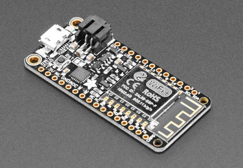
Adafruit Feather HUZZAH ESP8266
for use with CircuitPython & Arduino IDE
Specs
- Measures 2.0" x 0.9" x 0.28" (51mm x 23mm x 8mm) without headers soldered in
- Weight 9.7 grams
- ESP8266 @ 80MHz with 3.3V logic/power
- 4MB of FLASH (32 MBit)
- Built in WiFi 802.11 b/g/n
- 3.3V regulator with 500mA peak current output
- CP2104 USB-Serial converter onboard with 921600 max baudrate for speedy uploading
- Auto-reset support for getting into bootload mode before firmware upload
- 9 x GPIO pins - can also be used as I2C and SPI
- 1 x analog inputs 1.0V max
- Built in 100mA LiPoly charger with charging status indicator LED, can also cut a trace to disable the charger
- Pin #0 red LED for general purpose blinking. Pin #2 blue LED for bootloading debug & general purpose blinking
- Power/enable pin
- 4 mounting holes ⌀ 2 mm
- Reset button
- It comes preprogrammed with the Lua interpreter (you can use the Arduino IDE or CircuitPython. See the links below)
To make it easy to use for portable projects, Adafruit added a connector for any of their 3.7V Lithium polymer batteries and built in battery charging. You don't need a battery, it will run just fine straight from the micro USB connector. But, if you do have a battery, you can take it on the go, then plug in the USB to recharge. The Feather will automatically switch over to USB power when its available.
Although this board costs more than an ESP8266-SMT board or an ESP8266-only board, it has some benefits.
For example this Feather board has a onboard USB to Serial chip, so you can connect directly to your computers USB.
So I think if you are a beginner with the ESP8266, it is much easier to start exploring the 8266 with the Feather.
And start using the ESP8266-SMT boards or ESP8266-only boards when you have gained some experience with the Feather.
I think this is a great chip for some fun wireless IoT stuff.
Although I refer to Adafruit for the ESP8266 SMT boards, there are other manufacturers who produce ESP8266 breakout boards.
These boards are ESP8266 only, which means there are no extra's on board. No voltage regulators, no level-shifters and no extra RAM. As you can imagine they cost a lot less, only a couple of Dollars.
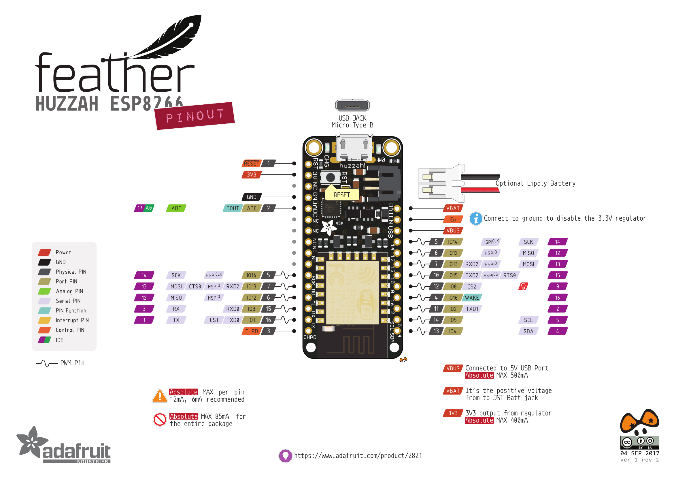
Pinout
Power pins
- 3V - this is the output from the 3.3V regulator, it can supply 500mA peak (try to keep your current draw under 250mA so you have plenty for the ESP8266's power requirements!)
- GND - this is the common ground for all power and logic
- BAT - this is the positive voltage to/from the JST jack for the optional Lipoly battery
- USB - this is the positive 5 Volt to/from the micro USB jack if connected
- EN - this is the 3.3V regulator's enable pin. It's pulled up, so connect to ground to disable the 3.3V regulator
Links
- To product page
- To Adafruits tutorial for all sorts of details, IDE instructions, pinout details, power management and more
- Everything ESP8266 Forum
MicroPython does support the ESP8266.